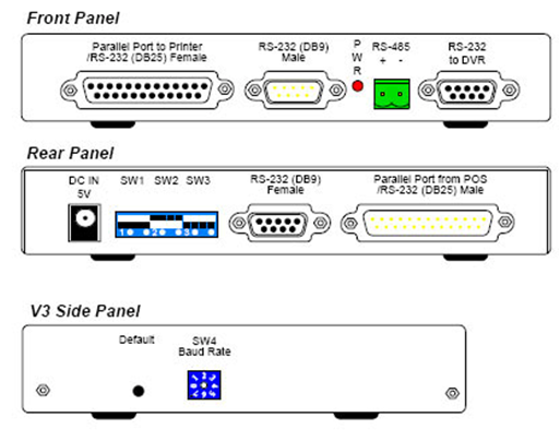
 | Overview the various components of GV-Data Capture V3 Series. |
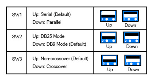 | To adjust the DIP Switches, refer to the diagram on the
right.
- If your POS system is parallel type, set DIP Switch SW1 to
Down; otherwise keep the default setting.
- If the output interface of your POS system is DB25, set DIP
Switch SW2 to Up; otherwise keep the default setting.
- If the cable connecting your POS system to the GV-Data Capture
is crossover, set DIP Switch SW3 to Down; otherwise keep the
default setting.
|
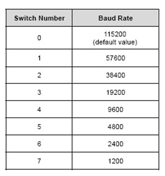 | To have the POS data transferred to the GV-System via the
GV-Data Capture, you need to set the exact baud rate in each
connected device, including the GV-Data Capture and POS systems.
On the side panel of the GV-Data Capture, there is a Baud Rate
Switch. Each number (from 0 to 7) on the Switch represents a
kind of baud rate. Set the baud rate to correspond to that of
the POS system. |
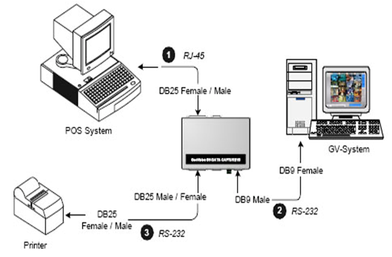
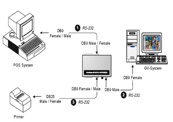 | DB25 Serial Interface The illustration below is an example of a POS system using a DB9-DB25 cable.- The RS-232 cables (1) and (2) are supplied with the GV-Data Capture.
- The RS-232 cable (3) is supplied with the POS system.
- The physical distance between the POS system and GV-System should be less than 10 meters (32 ft).4) Control Panel --> Windows Firewall
|
 | Parallel Connection To connect a parallel POS system, two
precautions should be taken:
1. Set DIP Switch SW1 on the rear panel of the GV-Data Capture
to Down. See 2.1 DIP Switch Setup.
2. If no receipt printer is attached, make sure to connect the
supplied Terminator to the GV-Data Capture (as illustrated
below), or the GV-System will not be able to receive any
transaction data.
- The Parallel cables (1) and (3) are supplied with the POS system.
- The RS-232 cable and Terminator are supplied with the GV-Data Capture.
|
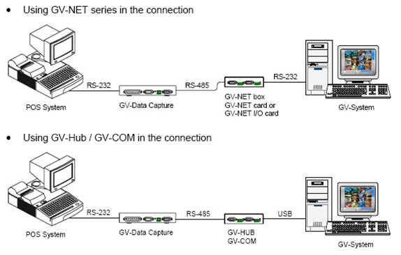 | The previous three diagrams assume the physical distance
between the POS system and GV-System is within 10 meters (32
ft). If the distance between the two devices is greater than 10
meters, it is required to use GV-NET series, GV-Hub or GV-COM in
the connection.
(Note: The maximum distance of RS-485 is 600 meters (2000 ft)) |
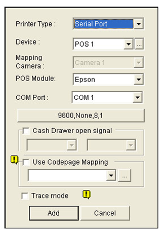 | Configure the GV-System to receive the transaction data from
the POS system.
1. Click the Configure button on the main screen, point to POS
Application Setting, and then select POS Device Setup. The POS
Server Setup dialog box appears.
2. Click the New tab. This dialog box appears.
3. After above settings, click Add to add the POS system to the
GV-System. |
