
How to setup your Camera System
Step 1: Unpack
Take out all of the components from the boxes. These should be your Cameras, DVR, Power supply, BNC cables, and DC cords
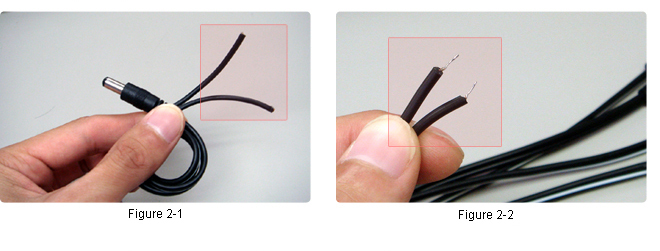
Next, using a Phillips head screwdriver connect the ends of each DC cord to the circuit board of the power supply.
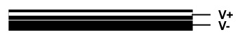
For All BLACK wires with WHITE STRIPE: |
|
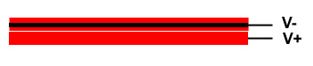
For All RED WIRES with a BLACK STRIPE: |
|
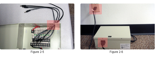
Lastly, after all of the DC cords are connected to the circuit board pull the ends out through the back hole of the power supply box (Figure 2-5) and plug in your Power supply to a wall outlet (Figure 2-6).
Step 2: Connecting your cameras to DVR and power supply
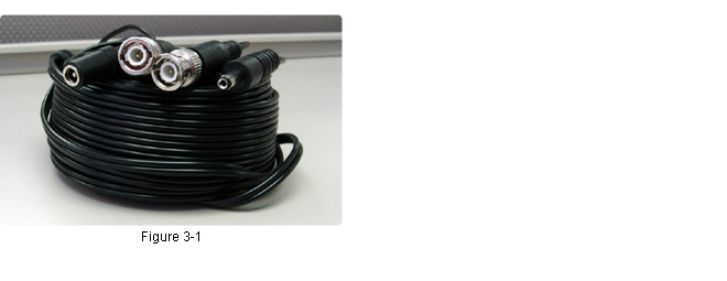
To connect your cameras to the DVR and Power supply you will need to use BNC cables (Figure 3-1).
*Note: You should have one bundle of BNC cables per camera.
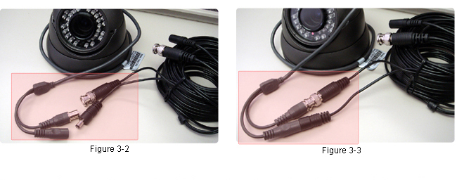
Connect your camera to the BNC cable (Figure 3-2 & Figure 3-3)
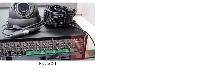
Next, connect the opposite end of the BNC cable to the back of the DVR Video In (Figure 3-4).
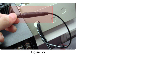
Lastly, connect the BNC cable to the Power supply DC cord. (Figure 3-5).
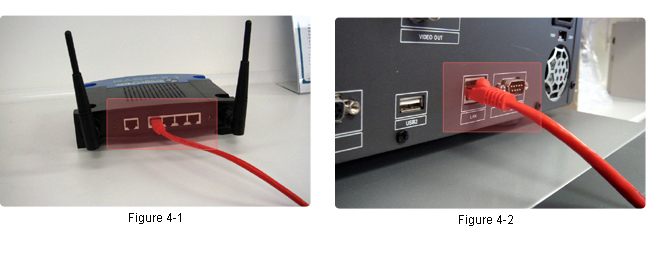
Step 3: Connecting your router to the DVR
Connect your network cable from your router (Figure 4-1) to the back of the DVR (Figure 4-2).
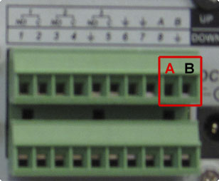
Step 4(Optional): Connecting a PTZ camera to the DVR
Use a very small Phillips Head screw driver to attach the red (POSITIVE) cable to the "A" box and the black (NEGATIVE) cable to the "B" box.
This completes the physical setup process!
{* OLD UNRESPONSIVE HTML CODE| Step 1: Unpack
Take out all of the components from the boxes. These should be your Cameras, DVR,
Power supply, BNC cables, and DC cords | |
| |
| Next, using a Phillips head screwdriver connect the ends of each DC cord to the circuit board of the power supply. | |
|
For All BLACK wires with WHITE STRIPE: BLACK w/ WHITE STRIPE = POSITIVE SOLID BLACK = NEGATIVE |  |
|
For All RED WIRES with a BLACK STRIPE: RED w/ BLACK STRIPE = NEGATIVE SOLID RED = POSITIVE |  |
| Lastly, after all of the DC cords are connected to the circuit board pull the ends out through the back hole of the power supply box (Figure 2-5) and plug in your Power supply to a wall outlet (Figure 2-6). | |
| |
| Step 3: Connecting your cameras to DVR and power supply
To connect your cameras to the DVR and Power supply you will need to use
BNC cables (Figure 3-1). *Note:You should have one bundle of BNC cables per camera. | |
 | |
| Connect your camera to the BNC cable (Figure 3-2 & Figure 3-3) | |
 | |
| Next, connect the opposite end of the BNC cable to the back of the DVR Video In (Figure 3-4). | |
 | |
| Lastly, connect the BNC cable to the Power supply DC cord. (Figure 3-5). | |
 | |
| Step 4: Connecting your router to the DVR Connect your network cable from your router (Figure 4-1) to the back of the DVR (Figure 4-2). | |
 | |
| Step
5 (Optional): Connecting a PTZ camera to the DVR Use a very small Phillips Head screw driver to attach the red (POSITIVE) cable to the "A" box and the black (NEGATIVE) cable to the "B" box. | |
| |
| This completes the physical setup process! | |


